Feel Amazing Every Day with Expert Fitness and Nutrition Coaching
Achieving optimal health and fitness requires more than just a quick workout or a temporary diet plan. It is a holistic approach that involves understanding the importance of regular exercise, proper nutrition, and mental well-being. With expert fitness and nutrition coaching, you can make sustainable changes that will help you feel amazing every day, inside and out. When it comes to fitness, there is no one-size-fits-all solution. Expert fitness coaches understand this and tailor exercise programs to suit your unique needs, goals, and current fitness level. Whether you are aiming to lose weight, build muscle, increase flexibility, or enhance endurance, a customized plan will set you up for success. Workouts should be challenging but achievable, designed to push you beyond your limits while preventing burnout or injury. A coach can guide you through strength training, cardiovascular exercises, mobility work, and recovery, ensuring you stay on track and motivated.
But physical activity alone is not enough. Nutrition plays a crucial role in supporting your fitness goals. Expert nutrition coaching takes into account your personal lifestyle, dietary preferences, and any specific goals you may have an Emilio personal trainer. Whether you are seeking to fuel your body for high-intensity workouts or simply aiming for a balanced diet, a professional nutritionist can provide you with a sustainable eating plan. Proper nutrition improves energy levels, enhances recovery, and helps with muscle growth, fat loss, and overall health. The combination of fitness and nutrition is essential for maintaining long-term health. A balanced, nutrient-dense diet ensures you get the right vitamins, minerals, and macronutrients to support your physical activity. For example, lean proteins are important for muscle repair, while healthy fats support joint health and provide energy for endurance exercises. Carbohydrates serve as fuel for workouts and help maintain a balanced energy level throughout the day.
By working with an expert, you can optimize your meal planning to align with your fitness goals, ensuring your body gets the right nutrients at the right time. Expert coaching also emphasizes the importance of mental health. Fitness is not just about physical appearance; it is about feeling good both physically and mentally. A coach can help you manage stress, develop a positive mindset, and stay consistent in your routine. Regular physical activity releases endorphins, which boost mood and combat feelings of anxiety or depression. Creating a routine that incorporates fitness, healthy eating, and mindfulness practices will lead to a more balanced and fulfilling lifestyle. Ultimately, expert fitness and nutrition coaching provides the guidance, support, and education needed to make informed choices that will positively impact your health. With the right approach, you will not only see physical transformation but also experience an increase in energy, confidence, and overall well-being. When you prioritize both fitness and nutrition with expert coaching, you will feel amazing every day.
...How to Interpret Check Valves in Process P&ID Diagrams?
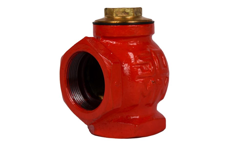
In process engineering, Piping and Instrumentation Diagrams P&IDs are essential tools used to design, operate, and maintain a system. They depict the flow of processes, piping, and instruments used in the system, and check valves are a crucial component that can be found in many of these diagrams. Interpreting check valves in P&ID diagrams requires understanding their function and how they are represented. A check valve is a type of valve that allows fluid to flow in one direction only, preventing backflow or reverse flow. This function is essential in many processes to avoid damage to equipment, protect pumps, and maintain the proper direction of flow in the system. In P&IDs, check valves are typically represented by a specific symbol, which distinguishes them from other types of valves. The standard symbol for a check valve is often a simple circle with a line running through it, often with a small arrow indicating the permitted direction of flow.

The symbol may also include additional markings, such as the type of check valve swing check or ball check and the size or material specifications. When interpreting check valves in P&IDs, it is essential to consider their placement in the diagram. They are often located in systems where backflow could cause operational issues, such as after pumps, compressors, or in systems involving sensitive chemicals or gases. The check valve symbol, accompanied by the direction of flow, gives insight into how the fluid moves through the system and where backflow protection is required. One important aspect to look for is whether the check valve symbol is shown with a dashed line or a solid line. Dashed lines often indicate the valve is in a bypass line or a secondary path. A solid line may indicate the valve is in the primary flow path. Understanding the context and the system’s flow conditions helps in interpreting the check valve’s role within the larger process.
Another key factor to interpret is the location of the valve in relation to other components. For instance, a check valve placed downstream from a pump is meant to prevent reverse flow that could damage the pump. If it is located near a pressure relief valve, it may serve to protect the relief system from backpressure. In addition to the basic functionality and positioning, the P&ID may include additional details, such as pressure ratings, material specifications, and operational conditions for the check valve. These specifications help engineers understand the exact requirements for selecting, installing, and maintaining the valve. Overall, interpreting check valves in p&id symbols diagrams involves understanding their purpose of preventing backflow, identifying the symbols used to represent them, and recognizing their placement within the process. By carefully analyzing the diagram and considering the context of flow direction and system function, engineers can ensure that the check valve performs its intended role in the system efficiently.
...